What are we checking?
There are 4 groups of calculations:
Current carrying capacity: to check that cables will not overheat in normal use
Voltage drop: to check that there is enough voltage at the load.
Risk of shock: to check that CPDs will operate within the allowed time
Thermal effects: to check cables will not be damaged by large fault currents.
RISK of shock
We can reduce the risk of shock when there is a fault if circuit protective devices (CPDsP operate within the times required by BS7671
Final circuits up to and including 32A 0.4s
Final circuits above 32A
And all distribution circuits 5.0s
Fast disconnection times need high fault currrents
High fault currents require a low impedance of the fault loop Zs
There are 3 ways to find out Ze
Measurement
This is the preferred figure, if it is avaliable
Eqntuiry
this means phoning the supply company, but they will usually just give the maximum for the type of earthing.
Calculation
this is usually impossible because you need details about the supply network conductors and transformer.
Unit resistance is the resistance of 1 metre of cable of a certain size.
(1) 2.5mm² PVC/PVC twin and earth 23m
(2) 10mm² SWA 8m (L-N-E) 3core
(3) 1.5mm² PVC SINGLES 12.5m
(4) 4mm FP2000 17m
(5) 25mm Tails + main earthing conductor 3.5m
(6) 16mm aluminium singles x23m
(7) R² for main bonding conductor 37m
To look up max Zs, we may need some or all of the following:
The type of protective device
the rating of the protective device.
The disconnection time required.
the protective conductor size.
Thermal effects
There are two methods of checking this:
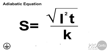
1. using the adiabatic equation
This is th preferred method
2. Using table 54.7 in BS7671
only use this if you do not have enough information for method 1.
s = minimum CSA of protective conductor
i = maximum earth fault current
We calculate this using
Uo
I=----
Zs use Zs from 3.
t = maximum disconnection time
k = a number we look up in BS7671 tables 54.2-54.5